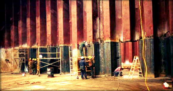
Corrugated bulkheads are generally utilised as the boundary between cargo tanks of small and medium sized product or chemical tankers. The corrugation provides benefits such as simplified cleaning which is highly desirable due to the operational profile of these vessel types. Properly designed, constructed and maintained corrugated bulkhead structures can give many years of safe and satisfactory service. On the other hand the complexity of structural configuration and difficulties of manufacture can lead to significant defects occurring which may be costly to repair. The following information is an extract from a Tanker Structure Co-operative Forum (TSCF) paper which reviews corrugated bulkhead design practice and provides details of damage experience from TSCF members.
Corrugated bulkheads can be categorised into two main groups based on the orientation of the corrugation; those with the corrugation orientated vertically and those with the corrugation orientated horizontally. Both types of orientation are found on transverse and longitudinal bulkheads. In the TSCF paper the following bulkhead arrangements are discussed:
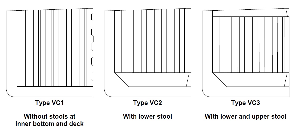
1. Vertically corrugated bulkhead
- Without stools at inner bottom – Type VC1. Type VC1 arrangement is most common on smaller tankers including product tankers and chemical carriers.
- With lower stool – Type VC2. This arrangement is utilised on larger ships than those using type VC1 and has found application on ships exceeding 40,000 dwt.
- With lower and upper stool – Type VC3. This arrangement is utilised on the largest tankers fitted with corrugated bulkheads which now reach Aframax size.
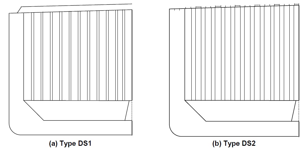
For bulkhead types VC2 and VC3, two deck supporting structure arrangements are described DS1 and DS2.
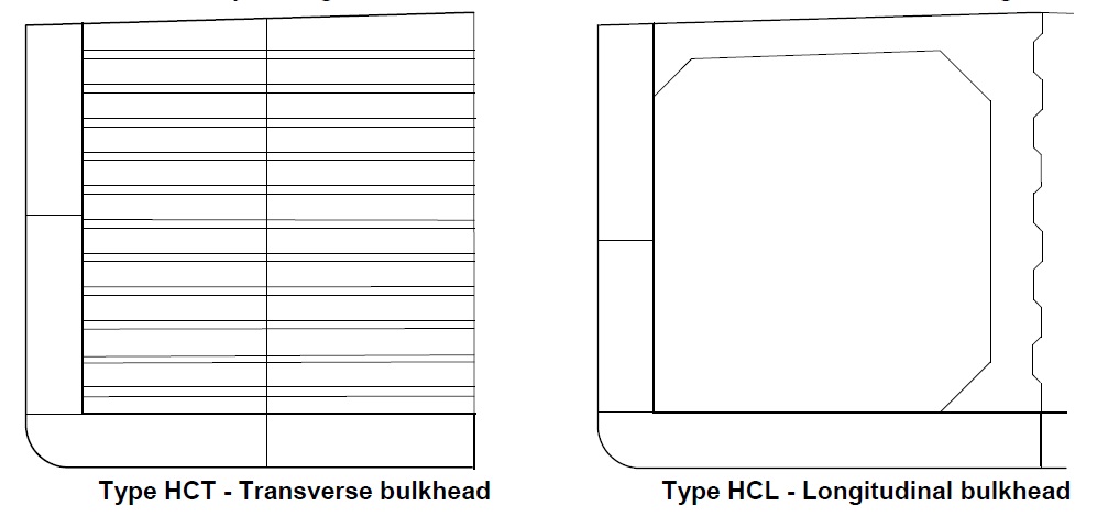
2. Horizontally corrugated bulkhead
- Bulkhead arranged transversely – Type HCT. This arrangement is most common on smaller tankers including product tankers and chemical carriers where the efficiency of tank cleaning is of primary importance.
- Bulkhead arranged longitudinally – Type HCL. This arrangement is most common on smaller tankers including product tankers and chemical carriers where the efficiency of tank cleaning is of primary importance.
Fractures Damage Type
In most cases fractures are found at locations where stress concentration occurs. Weld defects or flaws are other areas where fractures are found. If fractures occur under repeated stresses which are below the yielding stress, the fractures are called fatigue fractures. In addition to the cyclic stresses induced by wave forces, fatigue fractures can also result from vibration forces introduced by main engine(s) or propeller(s), especially in the afterward part of the hull.
Fractures may also occur in way of outfitting attachments and where lifting lugs used during ship construction are fitted in high stress areas and not properly removed. Fractures may not be readily visible due to lack of cleanliness, difficulty of access, poor lighting or compression of the fracture surfaces at the time of inspection. It is therefore important to identify, clean, and closely inspect potential problem areas. If the initiation points of a fracture are not apparent, the structure on the other side of the plating should be examined. Fractures initiating at latent defects in welds more commonly appear at the beginning or end of a run of welds, rounding corners, or at an intersection. Special attention should be paid to welds at the base of corrugations, at scallops/cut-outs, and at intersections of welds. Fractures may also be initiated at welds with an extreme undercut.
Typical locations susceptible to higher stress levels and misalignment are listed below. Such locations will then, by their nature, be at risk of damage unless appropriate measures are taken at the design stage:
Typical Small Tankers – Transverse Bulkhead – Vertically Corrugated
- Connection of corrugation to inner bottom.
- Connection of corrugation to deck.
- Connection of deck longitudinals to corrugations.
Typical Small Tankers – Transverse Bulkhead – Horizontally Corrugated
- Connection of corrugation to longitudinal bulkhead and inner hull.
- Connection of inner bottom and bottom shell longitudinals to floors in way of the lower stool.
Typical Larger Tankers – Transverse bulkhead – Vertically Corrugated
- Connection of lower stool to inner bottom plating.
- Connection of lower stool to lower shelf plate.
- Connection of vertical corrugations to lower stool plate.
- Connection of vertical corrugations to upper stool plate.
- Connection of longitudinal deck girder system to upper stool.
- Connection of upper and lower shelf plates to stool.
Buckling Damage Type
Buckling is caused by excessive compressive and/or shear stresses resulting in out-ofplane deformation. The buckling strength of a plate depends on the ratio of thickness to stiffener spacing. In the case of corrugated bulkheads the stiffening of the flange is made by the corrugation web. Buckling can therefore occur:
- Where corrosion has reduced the steel thickness, and hence the buckling strength.
- Where high loads have caused distortion (e.g. over-pressurisation, contact damage etc).
- When the welds between the components of the corrugation are degraded by corrosion, leading ultimately to detachment and reduction in buckling strength.
- Where initial deformation has reduced the buckling strength.
Once buckling has started, collapse may progress rapidly due to the relatively low ultimate strength capacity of the corrugated bulkhead panel. Corrugated bulkheads have a relatively low ratio of ultimate load carrying capacity compared to its elastic load carrying capacity. Typically the plastic moment transmitted by a corrugation is only 1.2-1.3 times the maximum elastic moment.
Local buckling is most commonly found towards the upper part of horizontally corrugated bulkheads where loads from over pressurisation are most significant. Elastic buckling will not normally be directly obvious but may be detected by evidence of coating damage, stress lines or shedding of scale. Buckling damages may also be found at the intersection between longitudinal and transverse corrugated bulkheads.
Deformation Damage Type
In addition to the deformation caused by buckling, deformation of structure can also be caused by out-of-plane loads or a combination of loads. Such deformation is often identified as local deformation, i.e. deformation of panel or stiffener, or global deformation, i.e. deformation of beam, frame, girder or floor, including associated plating. Deformations are often caused by impact loads/contact and inadvertent overloading.
Material Wastage Damage Type
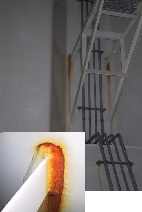
Material wastage of corrugated bulkheads on double hull tankers is relatively low. Corrugated bulkheads are generally fitted to product or chemical tankers and are therefore fully coated, well maintained and not subjected to mechanical wear. The surface of corrugations is almost free from surface stiffening which means that the incidence of grooving is reduced compared to stiffened structures where regular patterns of drainage can develop. However where brackets or outfit items such as access ladders or pipework are attached to bulkheads, accelerated corrosion can occur in way of coating breakdown at the attachment points. Internal corrosion of stool spaces is possible in way of coating breakdown particularly where these spaces are arranged for the carriage of water ballast.
Damages due to Detail Design
Detail design refers to the part of the design process, where attention is paid to minimisation of stress concentrations in highly stressed locations. Damages due to detailed design occur in highly stressed areas of corrugated bulkhead as summarised below
- In way of backing structure below the connection of the lower part of the corrugation to the adjacent structures.
- In way of backing structure above the connection of the upper part of the corrugation to the adjacent structures.
- In way of intersections of longitudinal/transverse bulkheads.
- Arrangements in way of longitudinal structures forming part of corrugated bulkhead supports.
Damages due to Insufficient Support
Provision of direct support for the ends of corrugations is important for all design types. This is especially true for the lower end of the corrugation which has relatively high end fixity due to the relative stiffness of the double bottom structure and variation of buoyancy loading on the bottom shell. The high end fixity is associated with high loads and it is therefore essential to provide adequate support. In all types of corrugated bulkhead design, the support arrangements generally represent a compromise in providing a structure compatible with production methods, whilst achieving a satisfactory level of load transfer between adjacent structural members.
Damages due to Lack of Continuity
The typical arrangements of corrugated bulkheads, present challenges to ensuring continuity of strength. When support is only provided for the corrugation flange an increased stress concentration at the corners of the corrugation flange is created. This increased stress concentration does not necessarily lead to damages provided design stress is low or detailed design calculations are made.
Damages due to Misalignment and Poor Fit Up
Whatever design steps are taken, stress concentrations are an intrinsic feature of the as designed structure. The fabrication process has significant extra scope to magnify intrinsic stress concentrations or introduce new ones due to misalignment and poor fit up.
At the ends of the cargo hold, where the hull shape results in changes to the height and slope of hopper structure, fit up of the corrugation and alignment of backing structure can be problematic.
Damages due to Welding
Weld defects are themselves associated with a significant stress concentration and such defects are therefore a common source of cracks in service. For newbuildings, according to Common Structural Rules (CSR) for Double Hull Oil Tankers (DHOT) increased requirements to welding (partial or increased fillet) apply to highly stressed connections in tension. Examples of locations are listed below.
- connection of hopper to inner hull
- longitudinal/transverse bulkhead primary support member end connections to the double bottom
- connection of corrugated bulkhead lower stool side plates to shelf plate and inner bottom/hopper tank
- connections of gusset plates to corrugated bulkheads
- connection of double bottom floors, lower hopper tank webs and double bottom girders below corrugated bulkhead flanges and gusset plates for corrugated bulkheads configured without lower stools
- structural elements in double bottoms below bulkhead primary support members and stool plates.
Full penetration welds are required at the following connections:
- lower end of vertical corrugated bulkhead connections
- lower end of gusset plates fitted to corrugated bulkheads
It should be noted that only full penetration welding can be inspected through the whole thickness by ultrasonic testing.
Damages due to Trough Thickness Lamellar Tearing
Lamellar tearing is a crack parallel to the rolled surface of steel plates in layers after welding. This is caused by welding stress, non-metallic inclusions in the plate, etc and it will be extended by further tensile strain in a direction perpendicular to the rolled surface. Such damage had been found mainly at inner bottom plates in way of corrugated bulkhead or stool shelf plating where full penetration welding had been employed and similar areas. Recently such incidents of damage have become less frequent because of improvements in quality, even for normal steel plates. However, the problem can still occur in steel made by older types of processes.
Under such circumstances, IACS CSR for DHOT requires consideration to be given to the use of special material (Z-grade steel) with specified through thickness properties for such areas. The interpretation of this requirement, however, shows the use of such material is not required in general according to the usual building standards and should be decided considering the level of tensile strain in direction perpendicular to plate and the plate thickness for avoiding lamellar tearing.
It is important to control the sulphur level of steel used in these areas, as a high sulphur content will create soft layers which will contribute to lamellar tearing, regardless of the thickness of the plate material.
More information regarding corrugated bulkhead damages of double hull tankers including recommendations on how they can be avoided can be found in the TSCF paper in the link identified below.
Source: Tanker Structure Co-operative Forum


Is it possible to have vertically corrugated bulkheads without lower stool but with lower hopper? If so, why is it not included in this list?