This incident information refers to bearing damage in the main engine of a tanker due to spark erosion. A tanker for oil was on a voyage in the Mediterranean Sea in loaded condition. The crew noted and monitored an abnormally high temperature in one of the main engine’s crankshaft bearings. Suddenly the lubrication oil pressure sank, the oil mist escalated in the crankcase and the engine had to be shut down immediately. The ship experienced a loss of propulsion and drifted for several hours. Finally, the cargo had to be unloaded from the vessel, which was then towed to a repair yard.

As a result one of the crankshaft bearings was severely damaged due to overheating and had to be completely replaced. It was concluded that the extensive wear of the lining was caused by spark erosion. The replacement of the bearing took 3 months (off-hire). The bearing shells were thoroughly seized to the bedframe due to the extensive heat and had to be removed by machining. Both the remaining bedframe and the crankshaft journal had to be thoroughly machined and polished on site in order for new bearing shells to be fitted.
When steel is immersed in sea water (e.g. a ship’s hull), small galvanic currents are initiated at anodic areas on the metal surface, causing corrosion. Such corrosion is predominately at the stern of a ship, where the combined effect of increased turbulence and differential metals results in accelerated corrosion rates. Many operators choose to combine a hull coating system with the installation of cathodic protection equipment which can automatically compensate for any damage to the hull coating and protect exposed metal areas, such as the propeller and propeller shaft.
The application of cathodic protection effectively suppresses the corrosion cells by applying an opposing current from external anodes. If the propeller is to receive the benefits of cathodic protection then there must be a continuous electrical circuit between the propeller and the ship’s structure.
This circuit usually exists when the propeller is at rest, when metal to metal contact is made between the shaft and the stern tube liners or main engine bearings and journals. However, a
turning propeller shaft on a ship is electrically insulated from the hull by the lubricating oil film in the bearings and by the use of non-metallic bearing materials in the tail shaft. Since the propeller presents a relatively large surface area of bare metal, it attracts cathodic protection currents, which tend to discharge by arcing across the lubrication film – even more if the lubrication oil is contaminated with water. Increasingly effective hull coatings also make the shafts more exposed to galvanic corrosion. This results in spark erosion which eventually leads to the pitting and ‘striping’ of the bearing metal. Excessive wear on the shaft bearings can often be traced to this cause.
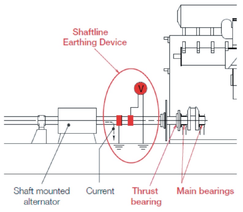
It was concluded that the extensive wear of one of the main bearings of the main engine in the incident discussed was due to spark erosion. This is most likely due to the shaftline earthing device not working as intended. In this situation, the electric potential between the crankshaft journal and the bedframe caused electric sparks to appear between the shaft and the bearing lining, which in turn caused extensive wear of the lining in a short space of time. Finally, metal to metal contact in the bearing caused the overheating, oil mist and emergency shutdown.
Lessons to be learned from such incidents include the following:
- Galvanic currents between the propeller shaftline and the ship’s hull may cause sparks which eventually leads to the pitting and ‘striping’ of bearing surfaces in the crankshaft, tailshaft and thrust bearings. This is avoided by ensuring proper electrical contact between the propeller shaft and the ship’s hull through an earthing device. The galvanic currents are caused by the steel hull – salt water – metal propeller/shaft system (galvanic cell), and may be increased additionally by such factors as a polished large size propeller (bare metal rotating in the water), sacrificial anodes and impressed current cathodic protection systems (ICCP). Engines may be more sensitive to spark erosion due to such bearing factors as reduced lining thickness, tin/aluminium lining (compared to white metal) and reduced oil film thickness. Earthing of the propeller shaft (electrical grounding) is a present DNV Rule requirement for all newbuildings. If not already installed, it is also recommended for all other vessels (also for vessels without ICCP). It is also best practice to use two earthing devices, one for the grounding and one for the monitoring of the potential difference (mV). The earthing devise is best placed close to the main engine to achieve an easy access and a dry environment.
- The shaftline earthing device is a simple and cheap investment compared to the results of the damage discussed, which involve the vessel becoming off-hire for 3 months due to the replacement of one main bearing.
- Regular maintenance of the shaftline earthing device is important, especially if it is mounted at the far aft end of the shaft and in a moist environment. Typical maintenance includes ensuring slip rings with a sufficient silver layer, brushes that are not worn out, appropriate contact between the shaft and slip rings and general cleanliness.
- The electric potential between the shaft and hull is for many installations kept track of by a permanently installed monitoring device which includes an mV meter. The effects of spark erosion are minimised when the potential across the shaft/hull interface is less than 50 mV. If the potential is read manually with an mV meter between the slip ring (or even better directly on the shaft, if possible) and the hull, the results are most relevant if the shaft is rotating and the main engine is running at normal speed.


Leave a Comment