The reduction of operational cost is an important aspect of managing a company especially in a harsh financial environment. In that way companies have the ability of saving financial resources for whatever purpose they want. In the shipping industry, fuel oil consumption is one of the most crucial parameters in defining each year’s budget.
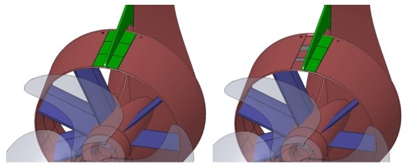
The Becker Mewis Duct (BMD) is a system that can be installed onboard ships making possible to either achieve significant reduction of fuel usage at a given speed or to allow the vessel to move faster for a particular power ratio. The BMD is comprised by fixed elements that are mounted/attached on the ship’s hull. These elements create a duct/nozzle, placed ahead of the propeller along with a fin system mounted within. This has the result of straightening and accelerating the hull’s wake into the propeller, producing also a clear forward thrust.

The fins mounted to the duct results in providing a pre-swirl to the ship’s wake which has the effect of reducing losses in the propeller’s slipstream, increasing also the propeller thrust at a specific power ratio. The effects of propeller slipstream loss reduction and propeller’s increase in thrust make a contribution to each other. The power savings that can be achieved from the BMD depend on the propeller’s thrust loading, which extends from 3% for multipurpose ships up to 8% for tankers and bulk carriers. The savings in fuel/power that can be achieved is independent of the draught of the ship and her speed.
The main advantages of the BMD system which are well known to the shipping industry are:
- Fuel savings in average 5-6%
- Fuel savings up to 8% in combination with a Becker Rudder
- Reduction of NOX and CO2 emissions
- Suitable for newbuildings and retrofits
- Reduced vibrations and pressure pulses
- No moving parts, no service necessary
- Return on investment in about 1 year
- Installation time 4 to 6 days approximately
The BMD combines in a non-linear interaction the principles of wake field equalization, reduction of propeller hub vortex and contra-rotating swirl. This has the result of harmonizing and stabilizing the flow, generating a pre-swirl which reduces rotational losses in the slipstream of the propeller. The fins have a constant effect which produces a pre-swirl in the opposite direction of the propeller operation, producing in that way additional thrust.The asymmetrically arrangement of the fins is due to create a homogenous flow distribution.
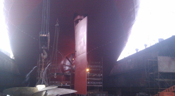
The BMD can be installed during regular dry dockings or even intermediate dry dockings, with the options ofhaving either the propeller in place or removed. An average installation time is 5 to 9 days without withdrawal of the tailshaft or with removal of the propeller and withdrawal of the tailshaft.
The process of installing the BMD is usually being made having help from a Becker specialist, who provides guidance and supervision with standard welding and fitting procedures (WPS approved from classification society).
BMD’s design is unique due to the fact that it is able to offer increase strength and stiffness.
Bellow we will make a step by step analysis to the installation of a BMD involving propeller removal and tailshaft withdrawal during an intermediate dry docking survey that took place in Neorion Syros Shipyards.
Step 1
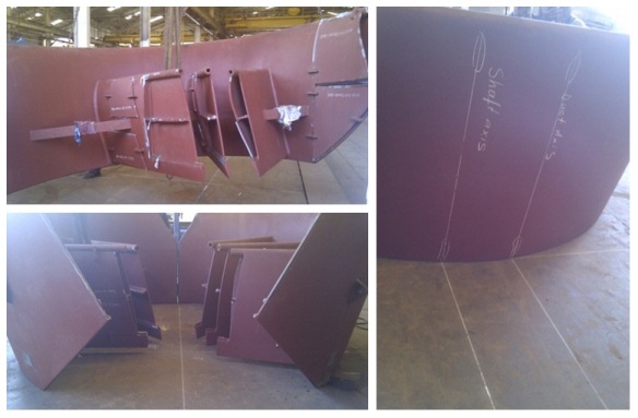
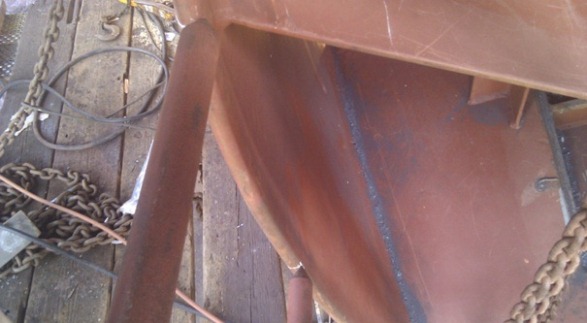
Positioning of the two side duct halves to an horizontal surface for taking measurements and reassuring that the prefabricated parts are similar to the drawings and that there are no deformations from the transportation of the parts.
Step 2
Once the measurements are completed there are two alternatives. Either the duct will be installed at one piece, either at two pieces. This is something that is decided each time from the shipyard.
If it is decided to proceed in one piece, then the 2 halves should be welded in the workshop and then transported to the ship for fitting. Otherwise if it is decided to proceed in two pieces then there is no need for any significant preparation in the workshop.
One way or another, in the workshop should be removed the covers which were secured on the duct for the transportation.
After deciding the way of fitting, then pad eyes should be installed-welded to the ship’s hull for the maneuvers and for the assembling of the duct.
Step 3
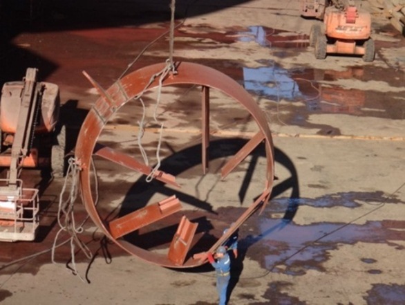
The most significant issue for the correct installation of the BMD, is the measurements accuracy during the fitting on to the stern tube area. This could be checked by several methods such as piano wire, total station theodolite TST, accuracy laser station or 3D gauge as it was fabricated in Neorion Syros Shipyards.
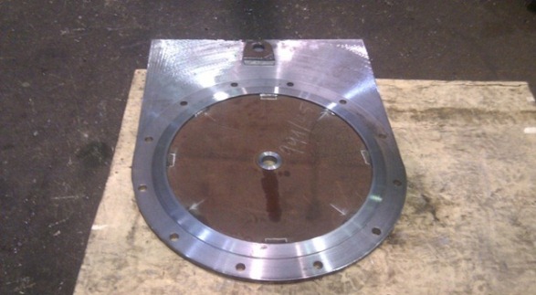
Steel plate machined
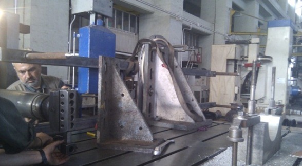
Accurate measurements (0,01mm) in boring machine
3D Gauge
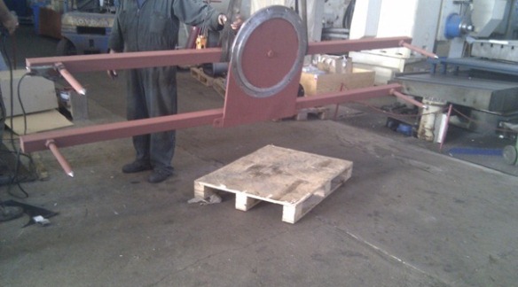
For better accuracy results, the 3D gauge was fabricated in boring machines in the mechanical workshop of Neorion and installed in the stern tube area were simplex fits.
Fitting of 3D Gauge
BMD Fixed Points
On the 2 halves of the BMD there is from construction some points which indicate Duct Axis and Shaft Axis. Once these points are fixed then the vertical levels are predefined, following ship’s and floating’s dock trim. Then only the correct installation regarding transverse distance remains, which is also indicated in the 3D gauge.
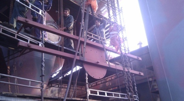
Step 4
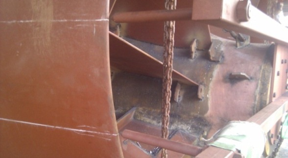
After positioning the duct halves and the 3D gauge, the plate fitters start trimming of the fins gradually until these are in the correct position. The trimming can be done in each side simultaneously if this is possible due to limited space. Trimming is continued until it is achieved the accepted limits of the 3D gauge so as to reach the final position of the duct.
Plate fitters working sequence is as mentioned, cropping fins, upper and lower part, checking the 3D gauge and repeating until the final position.
Final position according to the 3D gauge
Step 5
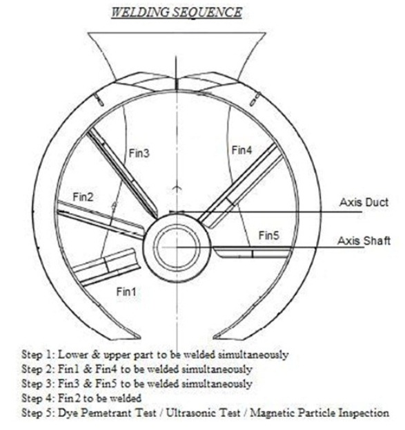
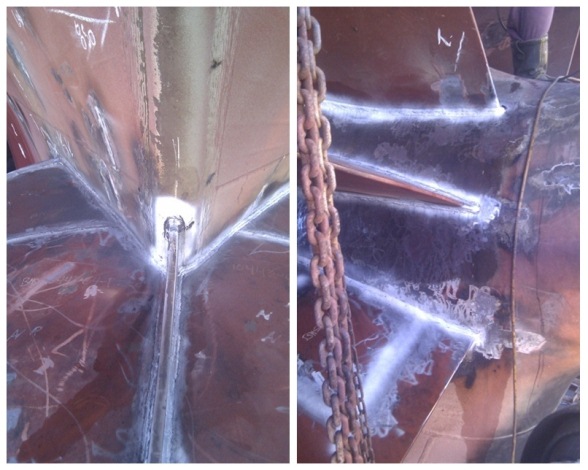
Once positioning is completed to its final position, then welding starts according to the yard’s prepared Welding Procedure Specifications (WPS), in accordance to the satisfaction of the attending Class surveyor.
It should also be noticed that preheating is also very important in all welding parts between ship’s hull and BMD. This is also mentioned in the WPS which are accepted from the class surveyor.
Step 6
After completing the welding sequence, following the approved WPS, then NDT should be done in way of all mounting welded parts.
Magnetic Particle Inspection
Step 7
After welding is completed then it should be closed all the assembly openings and welded. After that NDT will take place again to the welded mounted plates.
Step 8
All weldings should be grinded so as to have smooth surface and in order not to interfere to the water flow.
Step 9
After completion of the installation, duct and fins should be sandblasted to SA2.5 and treated according to the applied painting system of the ship’s hull.
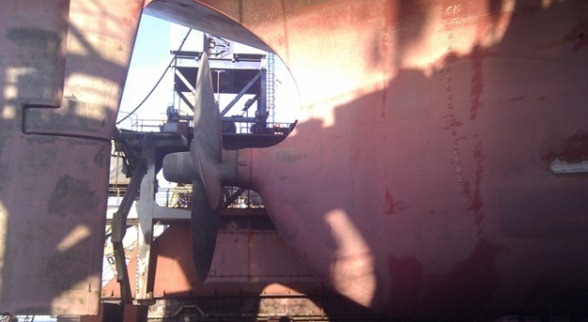
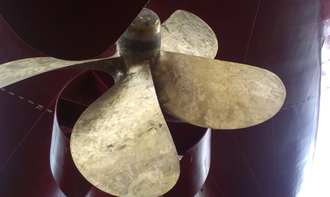
Assembling of the tailshaft along with the intermediate shaft and the propeller
SA2.5 and painting of stern area
Completion of installation of Becker Mewis Duct
Completion of installation of Becker Mewis Duct
The below is a summary (reference only) of the schedule for the installation of becker mewis duct.
Day 1
- Docking
- Pad eyes welding
- Staging iwo stern area
Day 2
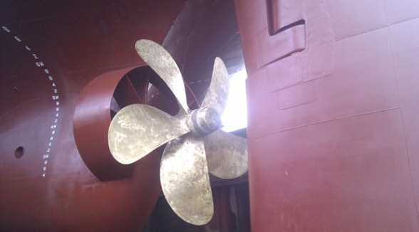
- Removal of prop cones cements
- Removal of prop nut
- Removal of propeller
- Removal of intermediate shaft
- Pulling inside the tailshaft
- Fabrication of 3D gauge
Day 3
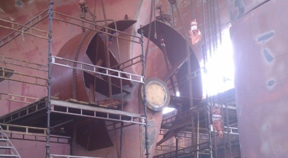
- Transportation of BMD pieces to the stern
- Hanging from chain blocks the 2 pieces of duct
- Completion of fabrication of 3D gauge (20hrs approx.)
- Starting the cropping from port side
Day 4
- Continuing the cropping PS and starting SS
Day 5
- Completion of PS BMD fitting
Day 6
- Completion of SS BMD fitting
- Starting of welding upper, lower part and fins
Day 7
- Completion of weldings
- Fitting and welding of mounted plates
- NDT to the weldings
- Grindings
Day 8
- Welding of mounted plates
- Grindings
- Pulling out tailshaft
- Intermediate shaft assembling
Day 9
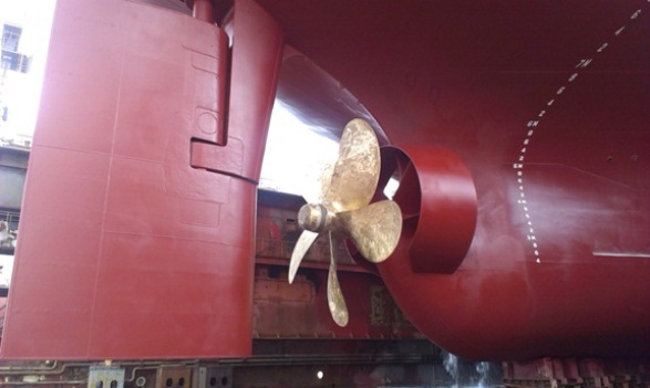
- Propeller fitting
- Propeller nut and cone fitting
- Filling oil the stern tube
- Mounting the rope guard
Day 10
- Undocking
ABOUT THE AUTHOR
 |
Nikos Kairis is the Co-founder of Officer of the Watch. He is a Naval Arcitect & Marine Engineer working in Neorion Syros Shipyards as Ships Repair Manager responsible also for the QA & QC Department of the shipyard. Nikos studied Naval Architecture & Marine Engineering in the National Technical University of Athens. His interests focus on exploring and finding new technologies applicable in the shipping industry. |


Leave a Comment