This investigation report refers to an accident that took place during an attempt to weld the casing head of a slip-on wellhead, gas flow was noticed coming from the +10 valve. Later, unsuccessful attempts were made to stop the flow, which was then coming from the drive pipe/surface casing annular region. The gas flow eventually ignited and caused extensive damage to the platform. The well bridged over and kill operations were completed successfully and fortunately there were no injuries.
Accident timeline
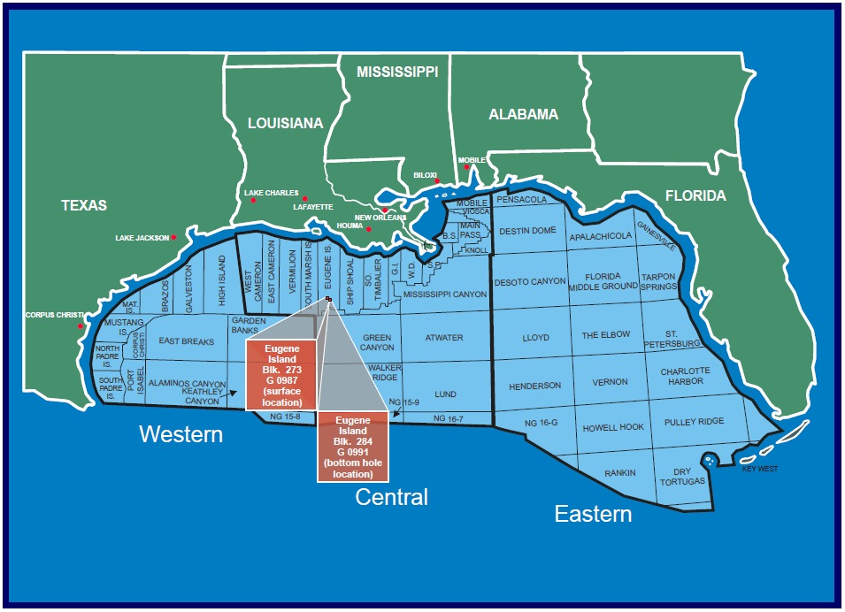
February 9, 2001 – The MMS Lafayette District approved Forest Oil Corporation’s Eugene Island Block 284, Lease OCS-G-0991, Well A-13 Application for Permit to Drill (APD). In the APD, Forest Oil Corporation proposed drilling Well A-13 to a measured depth (MD) of 5,476 feet and a true vertical depth (TVD) of 5,153 feet, using the Ensco 51 jack-up rig. The well would be located in 191 feet of water. Forest Oil Corporation anticipated driving the 24-inch drive pipe to a measured depth of 441 feet MD (441 feet TVD), drilling a 22-inch conductor hole and setting 16-inch conductor casing at 650 feet MD (650 feet TVD), drilling a 14¾-inch surface hole and setting 10¾-inch surface casing at 1,900 feet MD (1,900 feet TVD), and drilling a 9-7/8 inch production hole and setting 7-5/8 inch casing at 5,476 feet MD (5,153 feet TVD).
February 16, 2001 – The Ensco 51 rig arrived on location and began preload operations. It is important to point out that Forest normally conducts simultaneous operations when drilling on pre-existing platforms. During this drilling operation, extra precaution was used by installing back-pressure valves in all 12 wells located on the platform.
February 22, 2001 – The 24-inch drive pipe was driven to 460 feet MD. A starter flange was installed on the 24-inch drive pipe and a 6-inch, air operated, remotely controlled full opening valve was installed at the +10 level.
February 23, 2001 – The 21¼-inch diverter was installed, function tested, and Well A-13 was spudded.
February 24, 2001 – A 22-inch hole was drilled to 670 feet MD/TVD. The hole was circulated clean and a 16-inch scab liner was run to 633 feet MD/TVD and cemented with full returns taken at the +10 valve (see figure below for well schematic).
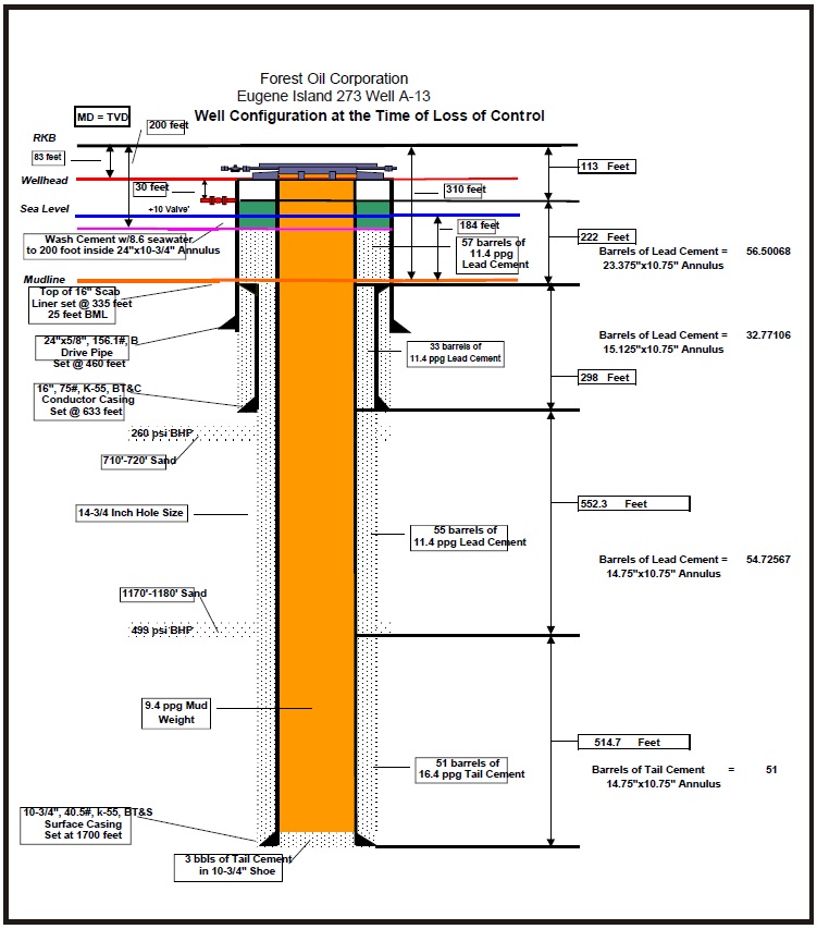
Figure above: Eugene Island Block 273, Well A-13, wellbore schematic.
February 25, 2001 – The diverter system was rigged up on the 24-inch drive pipe and the 16-inch conductor casing was successfully tested to 200 psig.
February 26, 2001 – The diverter system was function tested and drilling operations continued to a depth of 1,700 feet MD/TVD. The well was circulated for one hour, approximately two bottoms up. The well was checked for flow; none was detected. A pill was pumped and the drill pipe was pulled out of the hole.
February 27, 2001 – A Schlumberger wireline unit was rigged up and the 14¾-inch hole was initially logged from 1,694 feet MD/TVD to 633 feet MD/TVD. A second log was run over the same section of hole. The logs showed sands at 710 feet MD/TVD and 1,170 feet MD/TVD. Once the logging tools were pulled out of the hole, a 14¾-inch hole opener was picked up and run in the hole to 1,700 feet MD/TVD, and no fill was detected.
February 28, 2001 – Running tools for the 10¾-inch surface casing were picked up, and the 10¾-inch surface casing was run in the hole to 1,700 feet MD/TVD. The BJ cement head was rigged up and the well was circulated with a 9.4-ppg mud (pumped two bottoms up). No gas-cut mud was detected and operations proceeded to cement the 10¾-inch surface casing (cement in place at 0930 hours). The drilling program then called for the washing of cement in the 24-inch drive pipe by 10¾-inch surface casing annulus (see figure above). This was accomplished by opening the +10 valve and running 1¼-inch wash pipe to a depth of 200 feet from the rotary-kelly-bushing (RKB). The drilling program also called for waiting on cement (WOC) a minimum of 8 hours before cutting off casing. During the period of WOC, the rig crew laid down the 1¼-inch wash pipe, removed the diverter lines, laid down the bell nipple, and rigged up to pick up the diverter. After WOC for 8 hours, the +10 valve was opened to drain the fluid in the 24-inch drive pipe by 10¾-inch surface casing annulus. The diverter was then picked up (1730 hours) to make a rough cut on the 10¾-inch surface casing. A hot work permit was filled out, the area was sniffed for gas, and a fire watch was established before welding/cutting operations began. The 10¾-inch surface casing was cut and the excess was laid down. After removing the diverter, a rough cut was made on the 24-inch drive pipe and the excess laid down. Final cuts began on the 24-inch drive pipe and 10¾-inch surface casing.
March 01, 2001 – Final cuts on the 24-inch drive pipe and 10¾-inch Control surface casing were completed. While final cuts were being made by the welder, the night tool pusher and night driller went down to the boat landing to examine a means of removing the +10 valve. The well was static at this time. The 10¾-inch slip-on wellhead (SOW) by 11-inch, 5,000-psi casing head was lowered down to the wellbay for installation. The SOW was set on the 24-inch drive pipe and 10¾-inch surface casing. The SOW was leveled. The area was sniffed for gas and the welder tacked the 24-inch base plate in four places. The SOW was preheated, with some grease present. Once the SOW was preheated, the welder began to weld on the inside of the SOW. After the 3rd welding rod was burned, a small blue flame was observed. The fire was extinguished and thought to be caused by grease from the wellhead. The area was sniffed for the presence of gas, resulting in no detection of any gas. Operations resumed welding inside the SOW; a second flame ignited and was larger than the previous flame. The flame was extinguished and the area sniffed for the presence of gas, resulting in the gas detector showing a maximum level of gas present.
March 01, 2001, 0130 hours – The night driller observed a slight flow at the +10 valve. The onsite Forest Company representative was alerted and was informed that gas and fluid were escaping from the +10 valve. The Forest Company representative immediately instructed the crew to close the +10 valve to establish additional hydrostatic head by using 8.6-ppg seawater. An attempt was made to add seawater to the annulus through a ½ -inch gap located between the base plate and 10¾-inch surface casing (see figure below).
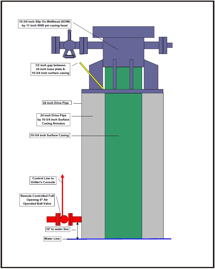
Figure above: Slip-on wellhead schematic and +10 valve schematic.
Because of the size of the opening on the base plate and the rate of 8.6-ppg water being added, sufficient volume could not be added to slow down the current well flow. At this point, rig personnel attempted to install another hose to add 9.2-ppg mud to the 24-inch drive pipe by 10¾-inch surface casing annulus. The flow of the well continued at an increasing rate. An attempt to increase the mud weight to 17.0 ppg was planned. Because of the rapid increase in flow, it was decided to add what was being mixed in the slug pit, which at that time was 16.0 ppg mud. It became difficult for the mud to flow at a steady rate because of the density and the size of the opening between the 24-inch base plate and 10¾-inch casing. As a last attempt to control the well, the Forest Company representative decided to open the +10 valve to allow the 16.0-ppg mud to displace the lighter fluid present inside the 24-inch drive pipe by 10¾-inch surface casing annulus. With the flow of the well increasing and all attempts of adding mud to the 24-inch drive pipe by 10¾-inch surface casing annulus failing, the +10 valve was closed.
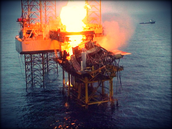
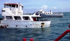
March 01, 2001, 0300 hours – A decision was made to evacuate the rig, and the +10 valve was opened in an attempt to divert flow away from the platform and rig (see photos below). The rig/platform was then abandoned.
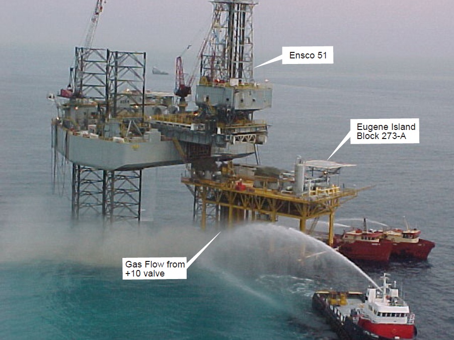
Photo above: Flow at +10 valve and fire monitors on location.
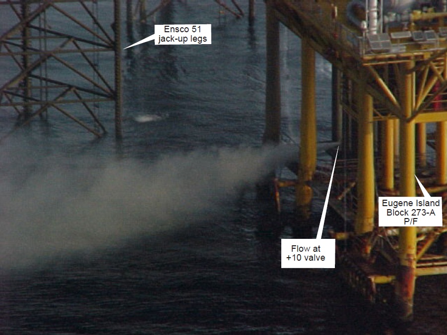
Photo above: Flow at +10 valve.
Personnel abandonment of the Ensco 51 and the Eugene Island Block 273 Platform A was accomplished in a safe and orderly fashion. Personnel mustered at the escape capsules and all 43 personnel were accounted for prior to departing the rig. Personnel boarded two escape capsules. In transit to BP-Amoco Eugene Island 273 Platform B, personnel maintained two-way hand-held communication. Personnel were later transferred to Forest’s Eugene Island 292 Platform B. There were no injuries as a result of the incident.
The Forest Spill Management Team was mobilized to respond to the incident. Representatives from Wild Well Control were called in for expert support and to plan and carry out capping and kill operations. Several boats deployed to the location by the Spill Management Team to spray the platform.
March 02, 2001, 0330 hours – Fire erupted on the Eugene Island 273-A Platform; source of ignition is unknown.
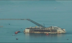
March 02, 2001, 0345 hours – Ensco 51’s derrick collapsed on the Eugene Island 273 A platform (see figure below). Because of the excessive heat, boats were unable to spray the platform continuously. Because the hydrocarbon flow was dry gas, dispersant application was not initiated and recovery action was not attempted.
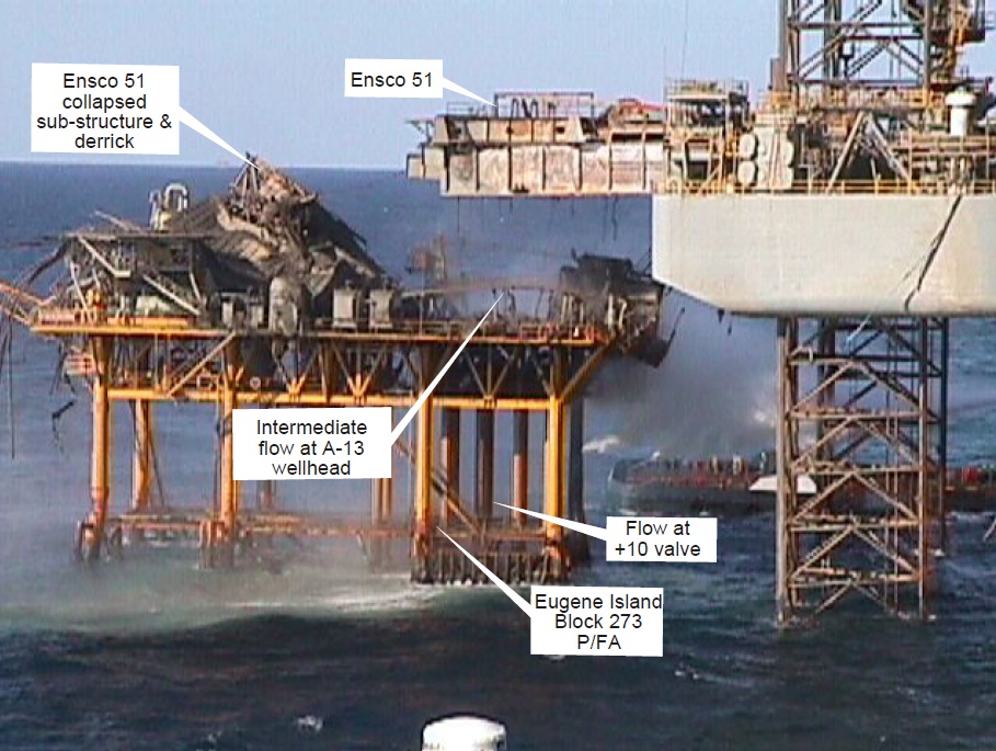
Photo above: Damage to platform and rig resulting from fire.
March 02, 2001, morning hours – Representatives from Wild Well Control flew to the scene to begin investigations and plan kill operations. The dynamically positioned derrick barge DB-50 was contracted for well control support. The Ensco 55 jack-up drilling unit was mobilized to the location to stand by to drill a relief well if needed.
March 03, 2001 – The well partially bridged and the fire went out. An initial visit was made to the platform by Wild Well Control representatives to assess the situation. The well flowed sporadically until the well bridged on March 5, 2001.
Numerous visits to the platform were made to remove debris around the wellhead to allow the installation of a Ventura Type “sliplock connection” over the 24-inch drive pipe. Once the Ventura Type “sliplock connection” was installed over the 24-inch drive pipe, a diverter and a BOP stack were installed to allow for safe kill operations (see figure below).
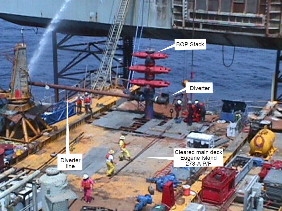
Photo above: Installation of diverter system and BOP stack.
A portable crane was mobilized to the location and installed on the Ensco 51 to allow for further removal of debris. Wells A-1 and A-5 were prepared for back-up relief wells. Stimulation boats were mobilized to the location for kill operations. A snubbing unit was mobilized to the location and rigged up. Using a 2-3/8 work string, well A-13 was reentered and cemented to the mudline on June 15, 2001.
The Ensco 51 substructure and derrick were completely destroyed in the blowout and subsequent fire. There was severe damage to the production platform and associated production equipment.
Root causes
The most vulnerable period for the cement is immediately after placement and prior to its setting. It is during this time that cement, while developing gel strength, becomes self-supporting and loses its hydrostatic pressure. This hydrostatic pressure loss is responsible for the well reaching an underbalanced condition, which can lead to gas invasion. Slurries must be designed with the idea of minimizing this vulnerable time when an underbalanced condition exists.
Formation gas migrated from the 700-ft sand and/or the 1,200-ft sand through the cement between the 24-inch drive pipe and the 10¾-inch surface casing, because of the above mentioned loss of hydrostatic pressure.
Additionally the following can be considered as contributing causes:
- Failure of Forest Personnel to communicate the presence of shallow-gas hazards to the contract cement service company. This resulted in cement not being properly designed to prevent gas migration into the cement.
- A prespud meeting was not conducted to communicate known shallowgas hazards to all parties involved in drilling operations.
- Once the hole section was logged and showed the presence of shallow gas, the well log information was not analyzed to verify that the cement program was properly designed for shallow gas.
- Opening of the +10 valve allowed the fluid level in the 24-inch drive pipe by 10¾-inch surface casing annulus to fall, reducing the hydrostatic pressure on the cement, which could have contributed to gas migrating into the wellbore.
Lessons to be learned
- Development of specific strategies to prevent gas migration into the cement column. These strategies include the use of special slurries with physical and chemical properties that inhibit or block the invasion of gas.
- Implementation of methods to improve communication of any presence of shallow-gas hazards to the contract cement company. Through proper communication, cement companies can design proper cement for gas migration.
- Development and put into practice of a policy of having prespud meetings on all wells with shallow-gas hazards.
- Design of procedures to ensure that log information indicating shallow gas is used to verify proper cement designs.
- Analysis of the safe use of the +10 valve where shallow-gas hazards are known to exist.
Source: BSEE


Leave a Comment