Monitoring of fuel consumption and GHG emissions from international shipping is currently under discussion at the EU level as well as at the IMO. There are several approaches to monitoring, each with different characteristics. Important differences exist with regards to the costs of the equipment, operational costs, the accuracy of the measurements, and the potential to monitor emissions of gases other than CO2. Moreover, some approaches offer more opportunities to improve the operational fuel-efficiency of ships and fit better to possible future policies than others.
Based on a survey of the literature and information from equipment suppliers, NGO Transport & Envronment published a report compiled be Delft, that analyses the four main methods for monitoring emissions.
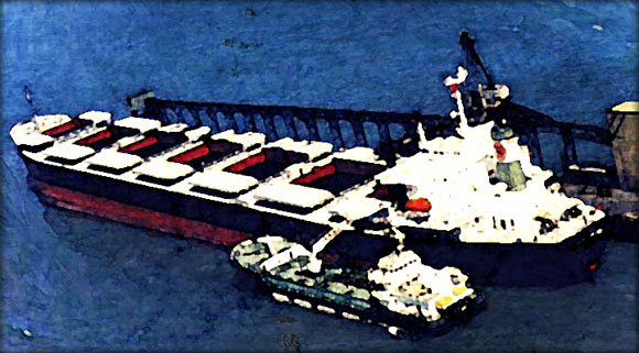
1. Bunker delivery notes
Bunker delivery notes are provided by the bunker fuel supplier specifying, amongst others, the amount of fuel bunkered.
There are IMO requirements in force (Regulation 18 of MARPOL Annex VI) that oblige vessels of 400 GT and above as well as platforms and drilling rigs to keep a record of the fuel oil that they bunker by means of a bunker delivery note (BDN).
Although the BDN is currently used for air pollution regulation purposes, it also contains information that may be used for the monitoring of fuel consumption in a certain time period and therefore to estimate CO2 emissions.
The BDN is issued by the bunker fuel supplier. The BDN has to contain at least the following information (MEPC.1/Circ.508):
- name and IMO number of receiving ship
- port
- date of commencement of delivery
- name, address and telephone number of marine fuel oil supplier
- product name
- quantity (metric tons)
- density at 15˚C (kg/m3)
- sulphur content (% m/m)
- a declaration signed and certified by the fuel oil supplier’s representative that the fuel oil supplied is in conformity with regulation 14(1) or (4)(a) and Regulation 18(1) of MARPOL Annex VI
According to Regulation 18 of MARPOL Annex VI, the bunker delivery notes have to be kept on-board for a period of not less than three years following the delivery.

AMSA Bunker Delivery Note Form
Note that information on the amount of fuel bunkered within a certain time frame is not sufficient for determining the amount of fuel that is used within this time frame because the tanks will most probably not be empty at the beginning and at the end of this period. Thus to establish a periodic fuel consumption, stock-takings at the beginning and at the end of the period are necessary too.
2. Tank sounding
Tank sounding is a system for measuring the amount of fuel in the fuel tanks.
The fuel consumption of a ship can also be determined by monitoring the tanks of the ship. Fuel tank levels are commonly measured on-board ships. This is also called tank sounding. The depth of the fluid from the surface to the bottom of the tank is thereby derived first and the corresponding volumetric quantity is then calculated. Sounding tables are necessary to convert tank level to volume. Typically, this is available in an approved form through the ship stability documentation. Fuel density information is necessary to calculate the corresponding mass. This is available from the BDN, however blending on-board may cause slight complications. Fuel temperature will also affect volume.
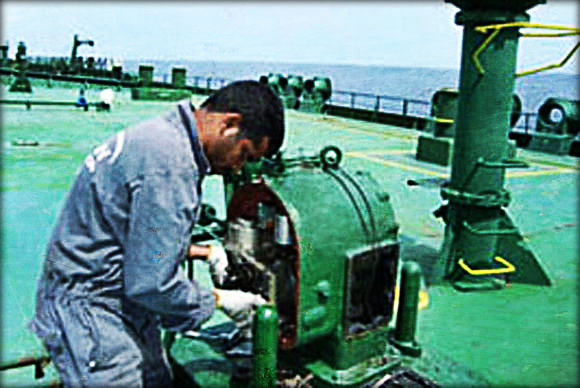
Image source: Marine Insight
Measuring the fuel tank levels can be done in several ways:
- Electronic sounding. In electronic sounding, a sensor is used which senses the pressure inside the sounding pipe or by sensing the tank pressure and sends a signal to the receiver. Here the signal is translated to the tank’s content value with the help of a PLC circuit. The value is displayed using electrical operated servo gauge or electrical capacitance gauge.
- Mechanical sounding. Mechanical provisions are made inside the tank so that the quantity of tank can directly be read through a level marker or an indicator or a float level sensor. In the tank a float can be attached to a pointer through a pulley. As the level varies pointer readings will change accordingly. A level gauge glass is also attached to the tank to read the quantity of the fluid inside the tank. The gauge may also be a pneumatic/hydraulic operated gauge or differential pressure gauge.
- Manually sounding. In this method, a sounding tape is used with a heavy weight bob attached to one end of the tape using a strap hook. It is the most commonly used method used for calculation of tank capacity. If the capacity inside a tank is more, free space of the tank is measured to calculate total capacity of the tank. This method is called ullage measurement.
When the content of the tanks on-board is monitored at two successive points in time, then the change of the stock that thereby is established only corresponds to the fuel that has been consumed in the meantime if no fuel has been removed for other purposes from the tanks or fuel has been added to the tanks, e.g. by bunkering, or fuel has been moved to other tanks. Thus in order to establish the fuel consumption of a ship within a certain period of time the tanks not only need to be monitored at the beginning and at the end of this period but also before and after fuel is removed from the tanks for non-combustion purposes as well as before and after fuel is bunkered.
Tank monitoring is a common practice in the sector, sounding frequency on a ship however differs from company to company and according to the working policy and the nature of operations going on board.
3. Fuel flow meters
Fuel flow meters are systems for measuring the amount of fuel supplied to the engines, generators or boilers. The fuel consumption of a ship can further be determined by means of flow meters. These meters allow for determining the amount of fuel that is flowing through the respective pipes.
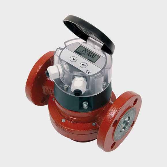
Image source: NAUTIC EXPO
The fuel flow is often measured directly (by volume, velocity or mass) or indirectly (inferential) by pressure. In order to capture all the fuel oil that is used on-board, all outward flows of all storage tanks on-board would actually need to be monitored. A wide variety of flow meters is available, such as electronic, mechanical, optical and pressure based.
- Electronic flow meters (volume). Electronic fuel flow meters (with digital display) are meters that are fitted to the main engine fuel supply and monitor fuel consumption constantly. The values recorded by the flow meters are calculated in the fuel flow calculation unit and form the basis for all other functions in the system.
- Velocity sensing flow meters (velocity). Velocity sensing flow meters are measuring the flow rate of the fuel based on the velocity. Examples of these meters are turbine flow meters and ultrasonic meters. Turbine flow meters are common in bigger ships. Turbine flow meters measure rotational speed of a turbine in the pipe which can be converted to volumetric flow. In many cases, fuel flow to the settling tank or day tank is measured rather than net flow to the engine which requires two flow meters (supply and return flow). Ultrasonic meters measure flow velocity from observations on a sonic wave passed through the flowing fluid, that exploit either a Doppler effect or time-of-flight principle.
- Inferential flow meters (pressure-based flow meter). Inferential flow meters do not sense flow rate through the direct measurement of a flow variable (such as volume, velocity or mass) but estimate flow by inferring its value from other parameters (differential pressure, variable area) They measure differential pressure within a constriction, or by measuring static and stagnation pressures to derive the dynamic pressure.
- Optical flow meters. Optical flow meters use light to determine flow rate. Small particles which accompany natural and industrial gases pass through two laser beams focused a short distance apart in the flow path. By measuring the time interval between pulses, the gas velocity is calculated.
- Positive displacement flow meters (volume). These meters measure flow-rate-based on volumetric displacement of fluid. They remain accurate at small fractions of rated capacity, but have relatively high head-losses; therefore they are generally suited to higher flow-rates. Mechanical parts of the meter are exposed to the fuel. If these were prone to wear or failure, such an event could potentially cause obstructed fuel flow. For this reason, the fuel meter should be installed with a by-pass leg. Examples of positive displacement flow meters include: oval gear flow meters, reciprocating piston flow meters, and nutating discs (wobble meters).
4. Direct emissions monitoring (i.e. measuring the exhaust emissions in the stack).
With direct emissions monitoring CO2 emissions are directly measured at the exhaust gas stacks.
Continuous emissions monitoring systems (CEMS) were historically used as a tool to monitor flue gas for oxygen, carbon monoxide and carbon dioxide to provide information for combustion control in industrial settings but are now also applied in the shipping industry to continuously collect, record and report the required emissions data. However, the technology is not widely applied in the maritime transport sector yet.
The standard CEM system consists of a sample probe, filter, sample line (umbilical), gas conditioning system, calibration gas system, and a series of gas analyzers which reflect the parameters being monitored. Typical monitored emissions include:
- sulphur dioxide (SO2)
- nitrogen oxides (NOx)
- carbon dioxide (CO2)
- diluent gases (CO2 or oxygen O2)
- flue gas velocity and opacity
Direct monitoring thus permits the combining of CO2 measurement with the measurement of other air pollutants.
The Delft report concludes that
- bunker delivery notes and tank soundings have the lowest investment cost.
- bunker delivery notes and tank soundings systems have higher operational costs than fuel flow meters or direct emissions monitoring because manual readings have to be entered in monitoring systems.
- Manually entering data in systems may result in errors. The costs of verification could therefore also be higher.
- Fuel flow meters have the highest potential accuracy.
- Real-time feed-back on fuel use or emissions, fuel flow meters and direct emissions monitoring provide ship operators with the means to train their crew to adopt fuel-efficient sailing methods and to optimise their maintenance and hull cleaning schedules.
- All systems allow for both time-based and route-based (or otherwise geographically delineated) systems.
- Because a ship can sail for several weeks after one bunkering, and is not restricted to routes or area, bunker delivery notes cannot be used to monitor emissions in a geographically delineated system.
- All systems can monitor CO2 and provide estimates of SO2 emissions.
- Only direct emissions monitoring can also monitor other exhaust emissions.
Source: Transport & Environment


Leave a Comment