A welding structure in order to have the required reliability, during her lifetime, it should have satisfactory quality. This means that it should:
- Be designed in a way that is appropriate for its sought use during its forecasting lifetime.
- Be manufactured from materials and welding methods according to the requirements.
- Be used and maintained rightly.
Welding quality is a relative term and this means that it is not necessary a construction to have better quality from what is needed according to the requirements. When the requirements are strict, that has as consequence the cost of production to be extremely high. On the other hand when the requirements are loose, that has as consequence the cost of maintenance to be high and the forecasting lifetime to be reduced.
")
The deviations in welded structures are classified to the following main categories:
Porosity
It refers to the gas pockets or voids free of any solid material, frequently found in welds. Porosity is caused when gas is released as a weld metal cools and its solubility is reduced, and from gases formed by chemical reactions in the weld. Porosity may be scattered uniformly throughout the weld, isolated in small areas, or concentrated at the root. Though in many cases, porosity is spherical, in some it is worm-shaped, and elongated in the so1idification direction of the weld metal. Porosity may be caused by excessive welding temperatures or incorrect manipulation.
")
Porosity
")
Porosity
Slag inclusions
This term is used to describe the oxides and other non-metallic solids that become entrapped in the weld metal or between the weld metal and the base metal. They generally come from the electrode covering material or from fluxes employed in the welding operations. In multilayer welding operations, failure to remove the slag between layers will result in slag inclusions in these zones.
")
Slag inclusions
Tungsten inclusions
In the gas tungsten-arc welding processes, the occasional touching of the electrode to the work or to the molten weld metal, particularly in the manual process, may transfer particles of the tungsten into the weld deposit. These tungsten inclusions generally are undesirable, and for critical work a limit on the size and numbers of these inclusions is specified.
")
Tungsten inclusions
Incomplete fusion
Incomplete fusion, or lack of fusion as it is frequently termed, is used to describe the failure to fuse together adjacent layers of weld metal or adjacent weld metal and base metal. This failure to obtain fusion may occur at any point in the welding groove. Incomplete fusion may be caused by: failure to raise the temperature of the base metal (or previously deposited weld metal) to the melting point, or failure to remove slag, mill scale, oxides or other foreign material present on the surfaces to which the deposited metal must fuse.
")
Incomplete fusion
Inadequate joint penetration
In this condition the joint penetration is less than that specified. Hence, partial joint penetration may or may not be a defect, depending on what is specified for that particular joint. Often “inadequate joint penetration” is used (improperly) to describe what is defined as “incomplete fusion” in ΑWS Α3.0-61 Definitions – Welding and Cutting. The AWS (American Welding Society) rationale is that “fusion” should be used when describing how completely the weld is bonded to or fused to the surface of the joint: “Penetration”, on the other hand, describes how far the weld extends into a joint.
")
Inadequate joint penetration
Undercut
This term is used to describe a groove melted into the base metal adjacent to the toe of a weld and left unfilled by the weld metal. It also describes the melting away of the sidewall of a welding groove at the edge of a layer of bead, thus forming a sharp recess in the sidewall in the area to which the next layer or bead must fuse.
")
Undercut
")
External undercut
Arc strikes
Although arc strikes are not normally considered defects, fractures (brittle and fatigue) frequently initiate from arc strikes. Arc strikes are formed during the unintentional melting or heating of areas outside the intended weld deposit area. They usually are caused by the welding arc but can be produced beneath an improperly secured ground connection. The result is a small melted area that can produce undercut, hardening, or localized cracking, depending upon the base metal.
Cracks
Cracks result from ruptures of metals under stress. Although sometimes large, they are often very narrow separations in weld or adjacent base metal. Cracks are one of the most harmful of welding defects and are prohibited by most specifications. However, small cracks, often called fissures or microfissures, may not reduce the service life. There are three types of cracks, having as criteria the position and the place that we find them, and are: i) longitudinal, ii) transverse and iii) crater. Specifications are reluctant to specify an allowable maximum crack size, rather, they tacitly admit that any cracks too small to be resolved by the required inspection procedure are permitted. Cracks in metallic structures can be characterized as ductile or brittle cracks, according to the type of fracture that takes place.
")
Cracks
Fracture is categorized according to the type of loading. Generally, fatigue cracks cannot cause the total failure of the metallic structure of the ship, and they are often observed in regions in the secondary structure of the ship. While the brittle cracks growths rapidly, for the fatigue cracks may need to pass years before they cause total failure to the structure. The cracks in metal structures can lead to the failure of the material either with a ductile either with a brittle fracture. The description of the cracks includes information about the behaviour of the cracks in the microstructure level, in order to become comprehensible the behaviour of the cracks in the level of the structure. Cracks in metallic structure of the ship are mostly ductile and derive from the fatigue of the structure.
")
Fracture Categories
The metal structure of the ship is vulnerable in cracks. Many statistical studies have shown that the presence of cracks is a serious danger for the ship. For certain type of ships, like Bulk Carriers, cracks are often met. Statistical studies has shown that the region of midship section is the most frail in the whole length of the ship, in the longitudinal distribution of cracks and the same is for the crack distribution in the bottom structure.
")
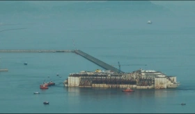
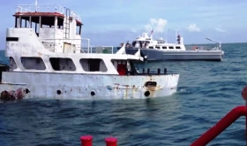
Damages in Side Plates in a B‐C


this site provide me many important information… with the help of this site…. m able to complete my project on hip building… thank you…