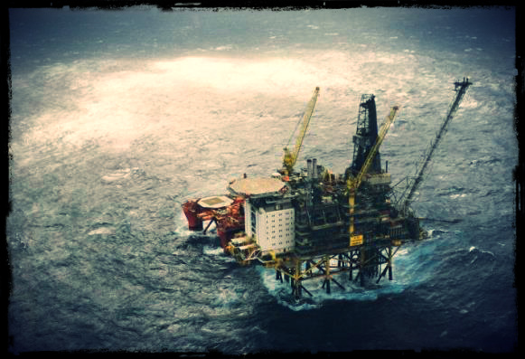
This incident investigation report refers to a hydrocarbon leak occurred September 2008 on Statoil Hydro’s Oseberg C installation. This leak occurred in the production manifold area. The initial escape was estimated at 26 kilograms per second. The immediate cause was a sudden and unintended opening of the test manifold valve leading to the unpressurised test manifold. The consequent pressure shock tore off a two-inch pressure equalisation pipe between the test and production manifolds. The direct cause of the pressure shock was the rapid opening of a well to the unpressurised test manifold. The fail-safe position of the activated control block opened the valve, while the deactivated one closed the valve in its fail-safe position. That meant a rapid and unintended opening of the valve when hydraulic fluid was introduced to the control block. The total hydrocarbon volume was estimated at 1,500 kg. No people were injured and material damage was slight.
Oseberg C came on stream in December 1991. Oil is produced from 18 wells. A multiphase pipeline carries oil from three of the wells to the Oseberg field centre for processing. Water is injected in three wells and gas in five to improve recovery. Oil production is about 30000 barrels per day. The oil passes through a separation train, with stabilised crude piped to the Sture terminal via the field centre. Oseberg C has simultaneous drilling and production.
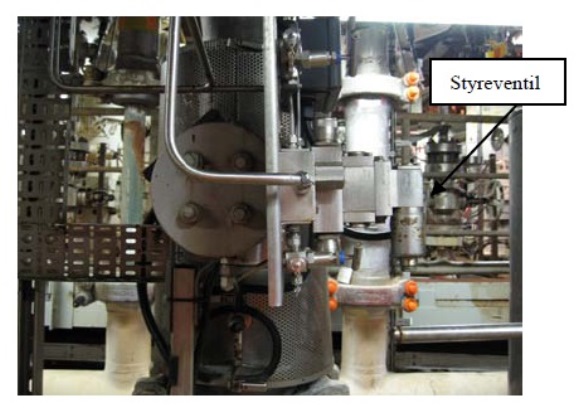
The wellstream from each well can be sent to either the test or the production manifold located in the M30 wellhead area (see figure below).
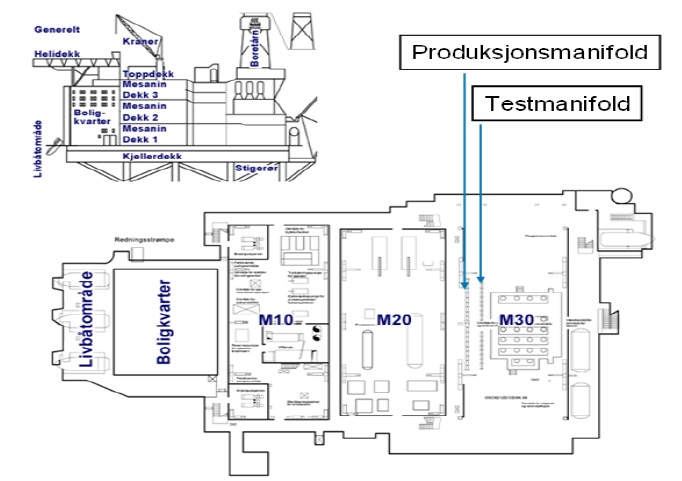
Manifold valves shut off or open for the wellstream from each well into the test or production manifold respectively (see figure below).
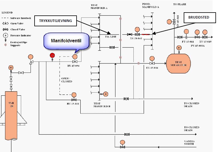
These valves are automatically controlled to leave one shut when the other is open (software interlock). They are normally operated from the central control room (CCR).
A pressure equalisation line connects test and production manifolds. This is used to pressurise the test manifold before the manifold valve is opened in order to avoid wear on the valve and a pressure shock in the test manifold. Both manifold and valve were manufactured in 22% chrome duplex stainless steel.
The actuator on the eight-inch valve from well C26, HV-15-096, into the test manifold was found in August 2008 (one month prior to the incident) to be malfunctioning. A work order was issued, and plans called for this job to be done on September 2008. The work permit was reviewed in a work permit (WP) meeting when a requirement was set to coordinate with the replacement of the orifice on the test separator, which was due to be done at the same time.
Course of Events
Work began at 16.30 on 12 September 2008. Two instrument technicians and a process operator were involved. Production was normal in the facility. The test manifold and downstream systems were depressurised but not drained. There was about 70 bar on the upstream side of the manifold valve, HV-15-096, and zero bar downstream. Replacement of an orifice was under way on the test separator. The repair was to be coordinated with this replacement.
The hydraulic control block due to be installed had been taken from the store. The electrical control signal was isolated and inlet and return lines for the hydraulic oil were shut off to the manifold valve. The hydraulic control block (see pictures below) was dismounted from the manifold valve.
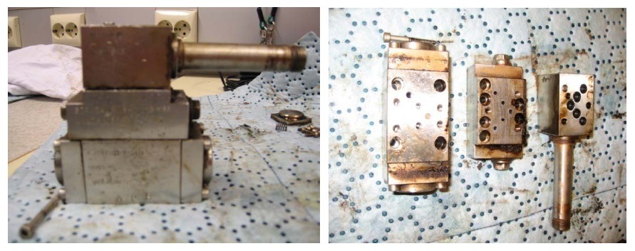
It was then discovered that the control valve was the mirror image of the one taken from the store (see picture below).
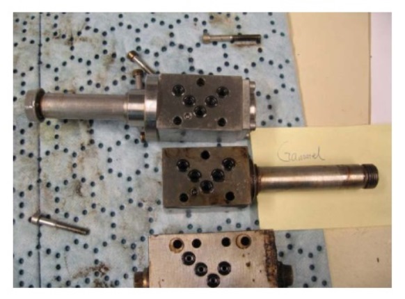
An investigation was launched to discover whether the part could be used, without contacting the discipline leader. Transferring the solenoid to the other side of the block was impossible. Nor could it be turned around. It could only be installed one way if hydraulic oil was to flow through the blocks. The other manifold valves were investigated out in the field, and it was concluded that the hydraulic control valve pointed both up and down (see picture below). On this basis, it was decided to install the hydraulic valve.
With hindsight, it transpired that no account was taken of the fact that the hydraulic system was installed on the other side of the installation plate and that the control valve accordingly pointed the same way.
The hydraulic block was installed and put back into place. Hydraulics, both inlet and return, were connected up. In order to leak-test the hydraulic block, the process operator opened the inlet line to hydraulic oil. Since the hydraulic system had been drained down and air-filled, the speed regulator did not work and the manifold valve opened rapidly and unintentionally. A pressure shock occurred in the test manifold and a two-inch pressure equalisation pipe was torn off the production manifold. The three people involved moved to a safe area. Production was swiftly shut down and pressure-relieved because gas was detected. The initial leak rate was calculated at 26 kg/s. Gas was detected at the air intake to the utility area. This led to the emergency shutdown of main and emergency power (ESD1).
Mustering went according to plan with the exception of reporting from the control room. That was because disconnecting ignition sources cut off power from the control nodes out in the plant. The monitors then went blank, and the normal sources of information disappeared. The ESD and fire and gas panels remained operational. ESD1 means the loss of normal telephone communication, and VHF must be used for external communication. This was in accordance with the design, but took the control room operators by surprise. They had not trained on this scenario. That meant messages about personnel on board (POB) remained for too long in the CCR.
Direct & Underlying Causes
The direct cause of the pressure shock was the rapid opening of well C26 into the unpressurised test manifold. The fail-safe position of the installed control block opened the valve, while fail-safe for the removed block closed it. This meant that, when hydraulic oil was introduced to the block, the valve opened rapidly and unintentionally. That was later verified by testing from the control room. When the control room gave the open signal, the valve closed and vice versa. It should also be noted that the wrong spare part remained in store after a modification during the commissioning phase. This component had the right part number except for one letter. Finally insufficient risk assessment was carried out when planning the work and those doing the job had inadequate competence about the hydraulic system.
In the event of possible ignition and a consequent explosion and fire, it is estimated that the material damage would not have been serious. Escalation of the incident was unlikely. It is not probable that the integrity of the installation would have been threatened but four people that were present in the area in the event of an explosion, they would have been killed.
Identified Non-Conformities
The incident investigation conducted by the Norwegian PSA identified the following non-conformities
- Insufficient competence. The workers involved in the incident, reported during the interviews conducted in the incident investigation that they have not received supplementary education/courses in hydraulics. They did not understand the significance of the solenoid being on the opposite side. Flushing and airing of the hydraulic system was not carried out before leak testing. The inlet valve was opened but not the return valve. Several of the hydraulic blocks showed signs of rough treatment, marks of blows.
- Lack of risk assessment and understanding. No risk assessment of working on a valve under a differential pressure of 70 bar, either during the WP meeting or during the actual execution of the work. The consequences of a rapid opening of the valve were not assessed. No coordination with work on the orifice. No consultation with the discipline leader.
- Lack of instructions. During the interviews, nobody could explain what was involved in “coordinating” the jobs. No instructions were given for how work on the hydraulic system was to be done. No instructions were given for working on valves under differential pressure.
- Inadequate design work. Insufficient pressure shock calculations were carried out for the piping system during the design phase. The wrong spare part was associated with the hydraulic system.
- Inadequate emergency response training. During the interviews, control room operators expressed surprise that normal telephone communication disappeared and the monitors went blank. Reports remained too long in the CCR when registering POB.
Material Analysis
From the available material investigations, it is clear that the duplex flange from the two-inch pressure equalisation line between the production and test manifolds on Oseberg C failed as a result of overload. The 45° fracture plane and the observation of dimples in all parts of the fracture plane (at micro scale: SEM investigation) confirm ductile overload and tensile direction in straight axial force.
Chemical analysis confirmed that the material in the flange accords with standard 22Cr duplex stainless steel, probably UNS S31803. The microstructure of the material was normal and as expected for forged duplex (austenite – ferrite), and hardness was also typical for this material grade. The general hardness was in the 241-253 HV10 range. Although some enhanced hardness (up to 347 HV10) could be observed close to the fracture, this was attributed to the work hardening experienced by the material as a result of the tensile load imposed on the pipe during the actual failure, and was accordingly normal. Based on the deformation and bending of the duplex material’s bond structure, a certain degree of fracture thinning in the order of 0.5-1 mm could be assumed.
The investigations show that the flange connection has been subject to fairly heavy grinding in association with the weld between flange and main pipe, and the minimum wall thickness has been measured at 1.9 mm in the 12 o’clock position as a result of the grinding. Assuming that fracture thinning has been 1 mm in this position gives an original wall thickness of 2.9 mm (compared with a nominal 3.91 mm). Weld macros in the various clock positions also show that weld repairs have been made around the whole circumference, but particularly in the 12 o’clock position. That explains the extensive external grinding in this area.
Tensile testing indicates relatively good strength values for the material, with the mean yield point and tensile strength being 564 and 723 MPa respectively. Taking the average value between yield point and tensile strength, this indicates that the minimum load under the actual failure was 316 kN (or 354 kN based on tensile strength alone), and also assuming an estimated fracture cross-section of 490 sq.mm. Since the fracture experienced some thinning, the minimum fracture load would probably have lain somewhere between 354 kN and 486 kN (the latter based on a nominal cross-section of 672 sq.mm and a wall thickness of 3.91 mm). For an average fracture thinning of 0.75 mm, the minimum fracture load would be 386 kN, which represents a 20 per cent reduction in load capacity compared with the nominal cross-section.
In addition to the purely external load, it should be mentioned that a tensile contribution has been made in solely qualitative terms by residual weld tension/extension. For duplex stainless steel, such tensions are typically close to the yield point and decline as a rule of thumb out to a length of 4 x wall thickness (in other words, about 15 mm for a wall thickness of 3.91 mm). In the present case, the fracture lies typically 2-7 mm from the weld and is accordingly well within the weld’s residual tension field.
Source: Norwegian PSA


Leave a Comment