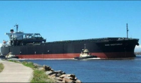
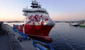
The form of a ship’s hull can determine the majority of its attributes; stability characteristics; resistance etc. As a result the power needed for a certain speed can also be determined along with the ship’s seaworthiness; maneuvering capabilities and load carrying capacity.
As it is shown on Figure 1 above three different lengths are used in order to define a ship.
- The Length Between Perpendiculars (lbp) which is the distance measured along the summer load waterplane between the aft and fore perpendicular. The aft perpendicular is taken at the aft side of the rudder post and the fore perpendicular ‘is the vertical line that intersects the forward side of the stem with the summer load waterline.
- The Length Overall (loa) is the distance measured between the fore and aft extreme points of the ship
- The Waterline Length (lwl) which is the length on the waterline where the ship happens to float.
Moreover, in Figure 1 the After Sheer and the Forward Sheer are also shown. Sheer is the measure of how much a deck rises towards the aft and bow. It can be defined by the height of the deck at side which is above the deck at amidships.
The mid-point between the perpendiculars is called amidships or midships.
The Beam is usually quoted at amidships and is most commonly quoted as the Moulded Beam which is the greatest distance between the two sides of the ship at its greatest width of the chosen section, as shown on Figure 2 above. The measurement is usually done between the inside of the ship’s plating. Except for the Moulded Beam there is also the Breadth Extreme which is measured to the outside of the ship’s plating but and it may also take into account any overhangs or flare.
The ship’s Depth, as displayed on Figure 2 varies along its length but is usually quoted for amidships. It can also be quoted Moulded Depth, which is from the underside of the deck plating.
Camber is defined as the rise of deck as it can be shown in Figure 2.
The height of the intersection between the extended out bottom line and the moulded breadth line above the keel is called Rise of Floor or Deadrise
The difference between the draughts on the bow and the stern of the ship is called trim. Trim is said to be by the bow or by the stern depending upon where the draught is greater.
The ship is said to hog or sag when the curvature is concave down or up respectively, as shown in Figure 3 below. The amount of hog or sag is the difference between the actual draught amidships and the mean of the draughts at the fore and after perpendiculars.
The shape of the hull can be defined by its intersection with three sets of orthogonal planes.
- The horizontal planes which are known as waterplanes and their lines of intersection known as waterlines.
- The transverse sections are defined by intersections of the athwartships planes.
- The planes which are in parallel to the middle line plane and cut the hull in buttock lines, the middle line plane defines the profile.
In the following Figure 4 the three orthogonal planes are displayed with three different colors along with the vessel’s section of each plane.
The form of a ship’s hull can be shown by the lines plan on Figure 5 below. This figure shows various curves of intersection between the hull and the three sets of orthogonal planes mentioned above. The curves are grouped in
- The Sheer Plan (intersections of the vertical fore and aft planes)
- The Half Breadth Plan (waterlines)
- The Body Plan (sections by transverse planes, the forward sections are shown to the right of the centerline, and the after sections are shown to the left of the centerline)
The distances of the various intersection points from the middle line plane are called offsets.
The displacement of a ship influences its behavior at sea. Displacement is a force measured in Newtons. For flotation, stability and hydrodynamic performance in general, displacement can be expressed in volume. Displacement can be defined as:
ρ = the density of the water in which the ship is floating
g = the acceleration due to gravity
=the underwater volume
For the fineness of the hull form a number of form coefficients is provided:
- Block Coefficient: This coefficient indicates whether the waterlines will have large angles of inclination to middle line planes and whether the form is full
Lpp is the length between perpendiculars
B is the extreme breadth underwater
T is the mean draught
is the underwater volume
- Coefficient of fineness of waterplane: A large waterplane coefficient in combination with a small block coefficient is favourable for the stability of the vessel.
AW is waterplane area
LWL is the waterline length
B is the extreme of the waterline
- Midship section coefficient: A low value of this coefficient indicates a high rise of floor with rounded bilges
AM is the midship section area
B is the extreme underwater breadth amidships
- Longitudinal prismatic coefficient: This coefficient is important for the resistance of the ship and therefore it affects the power of propulsion needed.
- Vertical prismatic coefficient: A large value of vertical prismatic coefficient indicates will indicate body sections of U-form and a low will indicate V-sections.


I have a doubt……does midship vary with waterplane or is it always the plane through the middle of perpendiculars? please reply through mail.
Midship doesn’t change anytime. It’s always remain the same as the draft change.
my concept is not clear about longitudinal cent.of buoyancy(LCB),LCF&LCG.
Why LCB & LCF changed in hydrostatic booklet as vsl’s draft chang.pls reply throug email.Thanks